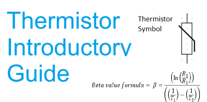
This is a guide of the fundamental characteristics of Thermistors. There are separate articles for specific topics on thermistors such as circuit design and online calculators.


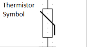
Thermistor circuit symbol
Thermistor is a word made from the combination of two words “Thermal” and “Resistor” Thermal + Resistor = Thermistor
Thermistors have no polarity.
The Thermistor is a widely used temperature sensing element that changes resistance exponentially with temperature.
Thermistors are the most cost-effective ways to sense and characterise changes in temperature.
Thermistor Resistance meaning
Thermistors resistance relationship with temperature is exponential not linear, this major characteristic is a huge consideration when designing the circuit that implements thermistors.

Note the exponential characteristics of the NTC and PTC thermistors on the left notice they are different from a straight linear graph shown on the right.
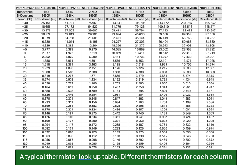
Thermistors will change resistance with temperature. A resistance v temperature table is available in any thermistor datasheet
Types of thermistors
There are two types of thermistors NTC or PTC.
NTC stands for Negative Temperature Coefficient, this means the resistance will Decrease with temperature increases.
- NTC thermistors are the more widely used between the two.
- Normally used as a temperature sensor element.
PTC Stands for Positive Temperature Coefficient, this means the resistance will Increase with temperature increases.
PTC thermistors are typically used for protection against over current and overheating.
The PTC will increase in resistance with temperature restricting current to the circuit under a overheating or over current condition eventually cutting out the power to the faulty circuit.
Thermistor values and what they mean
Base resistance
Thermistors are referenced to their base resistance this is at 25°C, meaning a “10K Thermistor” will read 10KΩ at 25°C.
Base resistances can vary and can be 1K Ω 2KΩ or 47KΩ etc, the value is selected for what best suits the circuitry or what the installed system specifies.
10KΩ is the most popular.
Tolerance
The tolerance value given for thermistors is provided as a percentage. Values can be 0.5%, 1%,2% or 5% etc.
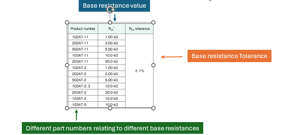
For example, if a Thermistor value is described as 10KΩ +-1% then at 25°C The Thermistor will measure between 9.9KΩ and 10.1KΩ. As shown below.

So resistance at 25°C will be 10K ± 100
If the tolerance was 0.1% then

So resistance at 25°C will be 10K ± 100
The percentage is calculated from the ideal resistance the thermistor should be at.
Due to the exponential change in resistance v temperature, this error can have different implications at different temperatures.
Meaning when the temperature is at the extremes 1% in error of resistance can mean +- 0.3°C at one extreme and 2°C at the other temperature extreme.
What are Beta Values or ‘B’ Values?
Thermistor Beta values also known as the B constant value quantify the specific change in resistance as the Temperature changes.
View the Beta Value Calculator
They are provided in the datasheet and specification of the thermistor.
Beta values are used to calculate the ideal resistance, to then determine the temperature.
How are Beta values found?
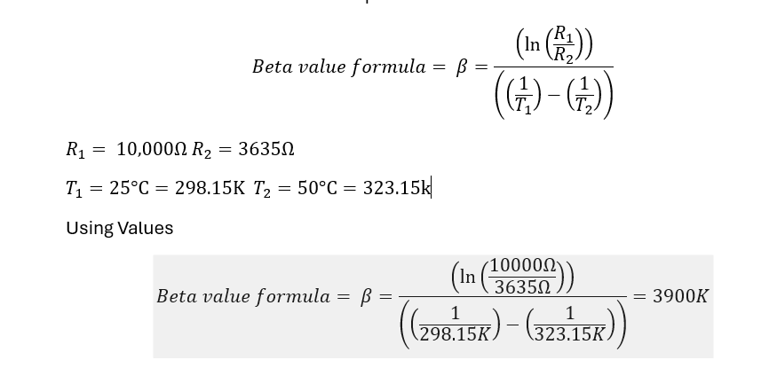
- Beta values are found using the Beta value formula between two resistances and their corresponding temperature.
- They are also given in the datasheet and named in the specification of the thermistor.
The B-Constant value is found in the datasheet with the temperatures that it was calculated across. In this case Beta value is given across 25°C and 50 °C

How to calculate Beta Values
The resistance table is available in the datasheet and is shown below ,The corresponding resistance can be found to the Temperatures referenced from the B-Constant Temperature 25°C and 50°C
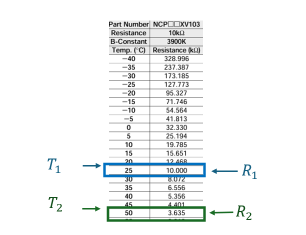
Therefore using the values above and the Beta value formula, lets prove how to calculate the Beta value it should equal 3900K
Using Values
